Use of integrated transformer test facilities
By EPR Magazine Editorial November 12, 2024 3:05 pm IST
By EPR Magazine Editorial November 12, 2024 3:05 pm IST

Static Frequency Converter (SFC) is designed to test all types of power and distribution transformers as it provides variable output voltage and variable output frequency.
Use of Integrated Transformer Test Facilities is slowly and steadily gaining ground in the transformer industry for routine, type & special test requirements as per IEC60076 for all type of power & distribution transformers.
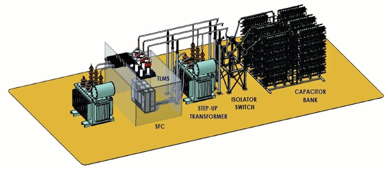
Image above- 3 D view of Integrated Transformer Test System
Integrated Transformer Test Facility (ITTS) is suitable for conducting following tests:
ITTS comprises of the following major equipment:
Schematic of Integrated Transformer Test System
Static Frequency Converter (SFC):
SFC is a state of the art Three Phase Frequency Converter which is built around an Intelligent Microprocessor Control along with IGBT based converter system which uses Sine Wave Pulse-Width Modulation (SPWM) for the system management. SFC is available for wide range of Power handling capacities starting from 50 kVA to 500 kVA with air cooled heat dissipation and from 500 kVA to 10,000 kVA with water cooled heat dissipation. Input power supply to SFC is 3 phase, 3 wire, 50 / 60 Hz which is first converted into DC Power Supply and then AC output power supply is regenerated from this DC Power Supply, which allows us to control the output voltage and frequency of this regenerated AC Power Supply.
SFC is especially designed for testing all types of power and distribution transformers as it provides variable output voltage & variable output frequency. SFC equipped with customized & highly efficient electronic control & software along with filtration circuitry provides high power quality output by eliminating high frequency distortions produced by fast switching semi-conductors (IGBTs).
Single SFC replaces 50 / 60 Hz motor-generator set, high frequency motor-generator set, and their respective voltage regulators and switchgears conventionally used for testing transformers. The compactness of SFC makes it suitable for use in mobile test facilities as well which was practically not possible with MG Sets. Additionally, it saves significant testing time as changing connections from one MG Set to another gets eliminated and also saves significant maintenance time required for regular maintenance of MG Sets.The Static Frequency Converter maintains efficient AC Power generation with typical efficiency in the range of 95-97% to operate all type of output loads; resistive, inductive or capacitive in nature. SFC provides overload, surge, short circuit, over voltage and over temperature protection to ensure best performance & enhanced reliability. All electronic parts are cooled by forced air and power devices are cooled by forced air or water circulation through heat sinks depending on the power rating.
SFC enables single/three phase testing without changing its connections and allows independent setting of voltage and frequency in both single and three phase modes. EMI filtering at the input ensures that high frequency noise is not transferred back to the grid. Special high frequency filtering coupled with common mode noise rejection filters allows the partial discharge measurement in a controlled shielded environment with specially designed isolated earthing. Additional low voltage and high voltage filters are provided for PD testing.
SFC allows injection of Harmonics in a controlled manner to test harmonic behaviour of power/converter duty transformers under test which is not possible with any conventional setup. High efficiency at nominal power with controlled voltage resolution of 0.1 V and frequency resolution of 0.1 Hz is available at the output of SFC. Besides SFC is modular in construction and its ratings can be enhanced at a later date as well if so desired and this too will not be possible with any conventional device.
Transformer Loss Measuring System (TLM):
TLM uses Standard Current Comparators instead of conventional CTs and Standard Capacitors instead of conventional PTs. The main advantage of the same is:
The output of standard current comparators and standard capacitors is then routed through signal processing electronics employing amplifiers to provide wide dynamic range while still maintaining the measurement accuracy before feeding the signal to power analyser. The signals measured by the power analyser is then transferred to the monitoring and analysing software where all computations as per IEC requirements are done and displayed. This software also allows to generate the complete test report of the transformer under test.
To summarize, the main advantages Modern Integrated Transformer Test Facility are following:
We use cookies to personalize your experience. By continuing to visit this website you agree to our Terms & Conditions, Privacy Policy and Cookie Policy.