Detecting Electrical Problems With Thermal Imaging
By EPR Magazine Editorial July 25, 2019 2:26 pm IST


By EPR Magazine Editorial July 25, 2019 2:26 pm IST

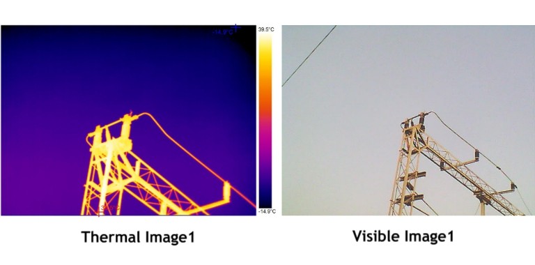
Thermal imagers produce live images of the heat emitting from equipment and are easy to use and much more affordable than just a few years ago. Today, this makes them highly practical and worthwhile solutions for even everyday electrical maintenance.
To use a Thermal Imager, a qualified technician or electrician has to point the imager at the equipment in question, scanning the required area for unexpected hot spots, then squeeze the trigger to capture an image. After completion of inspection, the saved images can be uploaded to a system for further analysis and reporting as well as future troubleshooting.
Thermal imagers are very simple to operate, but are most effective when used by qualified technicians who comprehend electrical measurement and understand the equipment to be inspected.
For anyone using a thermal imager, the following three points should be given attention:
• Point 1: Loading of Equipment
In order to effectively detect problems with a thermal imager, the electrical equipment being inspected must be under at least 40% of the nominal load. In fact, if possible, maximum load conditions are ideal.
• Point 2: Safety & Protection
Electrical measurement safety standards still apply under NFPA 70E[1]. Personal Protective Equipment (PPE) is compulsory when standing in front of any open, live electrical panels.
Equipment should include flame-resistant clothing, leather-over-rubber gloves, leather work boots, arc flash rated face shield, hard hat, hearing protection or a full flash suit, depending on the situation and the incident energy level (Bolted Fault Current) of the system to be scanned.
Thermal imaging is a comparative or qualitative process, when undertaken for performing electrical inspection. Typical temperature measurements are usually not required. Alternatively, one should aim to look for spots that are hotter than similar equipment under the same load conditions – unexpected spots.
Troubleshooting Electrical systems
Specific things should be checked when pursuing inspections related to breaker problems or wanting to check on load performance issues. As a rule, after any repairs, another follow-up thermal scan should be done. A successful repairing would mean no more unexpected spots along with earlier detected spots to have disappeared.
Keep in mind that not all electrical hot spots that show up are loose connections. For an accurate diagnosis, it is always recommended to have a qualified electrician either execute the thermal scan or be present while it’s being performed.
For three-phase discrepancies
Capture thermal images of all electrical panels and other high-load connection points such as drives, disconnects, controls, etc. Higher temperatures discovered through hot spots, should be followed and circuits, associated branches and loads should be examined.
Check for temperature differences by comparing the three-phases side-by-side. A cooler-than-normal circuit or leg might also signal failed components. More heavily loaded phases would appear warmer. Hot conductors may be undersized or overloaded. It is important to follow up with electrical or power quality measurements so as to accurately diagnose the problem, since an unbalanced load, an overload, a bad connection and/or harmonics, can all create similar patterns.
Keep in mind that voltage drops across the fuses and switches also can show up as unbalances at the motor and as excess heat at the root trouble spot. Always double-check current measurements with both the thermal imager and a multimeters or clamp meters before assuming the final cause.
 Connections and wiring issues
Look for connections that have higher temperatures than other similar connections under similar loads. These could indicate loose, over-tightened or corroded connections with increased resistances. Connection-related hot spots usually—but not always— will appear warmest at the spot of resistance, cooling with distance from that spot. Sometimes, a cold components might be abnormal due to the current being shunted away from the high-resistance connection. Broken or undersized wires or defective insulation may also be found. The NETA (Inter-National Electrical Testing Association) guidelines advise that when the difference in temperature (DT) between similar components under similar loads exceeds 15 C (~25 F), immediate repairs should be undertaken.
Fuse Issues
In case a fuse shows up as a hot spot on a thermal scan, it may be at or near its current capacity. Although not all problems show up as hot spots as sometimes, a blown fuse would be indicated as cooler than normal temperature.
Motor control centers (MCC)
Bus bars, controllers, starters, contactors, relays, fuses, breakers, disconnects, feeders and transformers – all the key components should be evaluated while checking an MCC under load. Each compartment should be opened, scanned and compared for relative temperatures, incorporating the foregoing guidelines for inspecting connections and fuses while wanting to identify phase imbalance.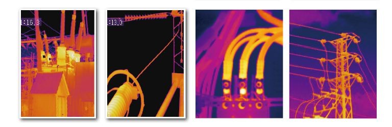 Transformer scanning
Thermal imagers can be used to check high and low-voltage for external bushing connections, cooling tubes, cooling fans and pumps, as well as surfaces of critical transformers in oil-filled transformers. Dry transformers will have coil temperatures much higher than ambient and it’s difficult to detect problems with thermal imagery.
Follow the previously noted guidelines for connections and imbalances. The cooling tubes should appear warm and in case one or more tubes appear comparatively cool, oil flow is probably restricted. Always remember that like an electric motor, a transformer also has a minimum operating temperature that represents the maximum allowable rise in temperature above ambient (typically 40 C). The transformer’s life would probably be reduced by 50% with a 10 C rise above the nameplate operating temperature.
(Note: A thermal imager will be able to detect an internal transformer problem, only if the malfunction generates enough heat to be detectable on the outside. This would mean, for example, that a malfunctioning bushing connection, will be much hotter than the surface temperatures read by the imager.)
CEM Instruments offers a wide range of innovative, high-specification and feature-full Thermal Imagers. The details for the same are available on their website www.cem-instruments.in or they can be contacted at their head office.
VIKRAM BHANSALI – Director
CEM Instruments (India) Pvt. Ltd.
32A Ganesh Chandra Avenue, 4th Floor
Kolkata 700013
Tel : +91 33 2215 1376
Email: info@cem-instruments.in
Web: www.cem-instruments.in
We use cookies to personalize your experience. By continuing to visit this website you agree to our Terms & Conditions, Privacy Policy and Cookie Policy.


-20251010140647.jpg)


-20251007141246.jpg)


-20251010134742.jpg)