Earth grid significance in T&D projects
By EPR Magazine Editorial July 5, 2019 11:44 am IST
By EPR Magazine Editorial July 5, 2019 11:44 am IST

Utility transmission and distribution network substation ground grids should ensure and improve the power quality. More importance is to be given towards safety, hence workers as well as the public working/entering the area need to be the top most priority in designing an earth grid (earth mat). Such earth grids are normally formed by the mesh of horizontally buried conductors. In addition to such a grid below ground level, earthing electrodes are driven into the ground and are connected electrically to the earth grid; equipment bodies, structures, neutrals etc. are connected to the station earthing system by earthing strips.
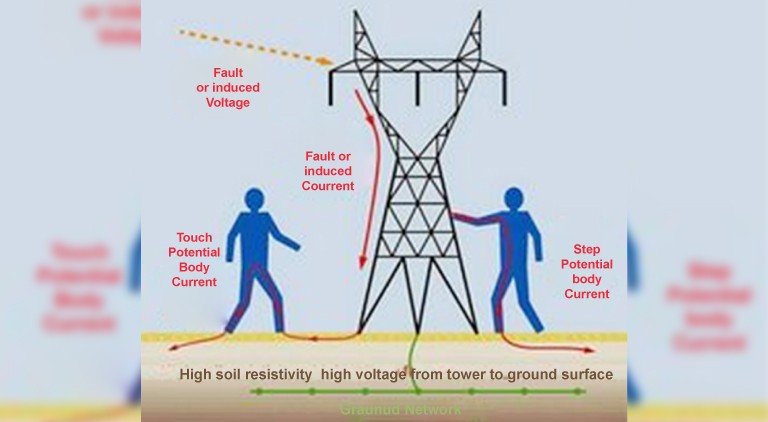
The grid design system should involve in mitigating the hazards arising due to step, touch potentials, in addition to bringing down the earth resistance. It should be capable enough to discharge the fault currents from overhead ground wires or from the lightning protection system and include ground path for surge arresters. The purpose is fulfilled only if the earth connections to structures and other non-current carrying metallic objects in the sub-station (equipment earthing) are collectively grounded to it.
In case if the grounding is not properly done, a fatal shock hazard due to potential difference between the feet while walking in or near the substation, especially, when the substation is experiencing a fault or lightning ground potential, raise. Only an utmost care while designing earth grid will substantially reduce the chance of anyone getting electrocuting within that substation yard area or in the periphery of the fence. A properly designed and implemented earth gird will form an equipotential bonding network.
Earth resistance
The value of earth resistance of the ground system determines the voltage rise of various earthed points during the earth fault. If earth fault current is I, earth resistance is R, the voltage rise under short circuit condition would be V= IR. The permissible potential rise and the maximum possible earth fault current sets a limit on the maximum value of earth resistance. To achieve earth resistance within specified limits, enough number of earth electrodes and sufficient surface area of the earth grid and closer ground mesh network are necessary. The touch potential and earth potential in the switchyard under any earth fault condition should be within safe limits. If the soil resistivity is high, the mesh rods are laid at closer spacing and more electrodes are inserted in the ground.
Earth resistance is purely dependent on the soil resistivity value at that measured location. The fence, equipment body, tanks, support, structures, towers, structural steel works, water pipes etc. should be earthed to the grid.
Designing of such earth grid should be done stage by stage in which every step carries an equal importance. The first and foremost step would be the site selection depending on the optimal grounding soil, carrying out of soil resistivity at the location which gives the basic or preliminary input for designing of the substation grid dimension. A Werner four pin method is practiced to check soil resistivity, the tests are to be conducted and diagonal measurements are recommended to avoid misinterpretation of value as the soil may contain rocky terrain in between when measuring. The figure below shows a sample software output of sensitivity plot derived out of measuring by Werner four pin method.
Mesh & vertical electrodes
The best configuration of the earth grid requires studying the effect of the parameters such as the length of the grid, number of mesh in the grid, the diameter or size of the earthing grid, depth of burial of the grid and effect of using vertical electrodes. Also, designing with multiple electrode alone will not reduce the ground resistance unless adequate spacing is maintained.
Multiple electrode closely spaced do not have a resistance reciprocally proportional to their number. There will be a sphere of influence generated around the electrode and hence IEEE 142 recommends “The distance between the two rods must be the depth of the first rod plus the depth of the second rod”. This characteristic is caused by the common mutual resistance in which the current of each raises the voltage of the other.
Case experienceIn a nutshell, describing and concluding what is significant for earth grid design and implementation and detailed configuration of ground mat design has to be analysed for the substation located in an area considering soil resistivity to make a safe ground mat. All the addressed issues are critical and due considerations during design in comparison with recommended practice in relevant IEC / IS / IEEE standards will help in overcoming technical and practical issues related towards implementation of the
required earth grid.
Article by:
Dr. K. Janakiraman,
Head-Technical,
OBO Bettermann India
We use cookies to personalize your experience. By continuing to visit this website you agree to our Terms & Conditions, Privacy Policy and Cookie Policy.