Thermography in Photovoltaic plants
By EPR Magazine Editorial September 10, 2019 3:23 pm IST
By EPR Magazine Editorial September 10, 2019 3:23 pm IST

Photovoltaic systems are an important contribution to properly utilise the solar energy and ensure sustainable development. In recent years, they have been one of the greatest sources of power and electricity. But with great results, there are some serious threats that tend to jeopardise the power output of the system. This makes the maintenance of the plants a significant aspect to tackle such threats concerning the functioning of a solar set up.
Potential threats to photovoltaic plants
Even a small technical defect is sufficient to have a considerably negative effect on the solar yield – and therefore the economic viability of a photovoltaic plant. The causes could be like carelessness during installation, degeneration of the laminates or slow damage due to years of UV radiation and weathering.
Some of the biggest problems that could be witnessed are:
Hotspots: Shadowed or defective module cells form an internal electrical resistance which can lead to undesired warming hotspot. Also, faulty or unsuitable bypass diodes (where shade is minimal) continue to lead to uncontrollable hotspots.
Delamination: The EVA protective layer may come away due to external influences. Any moisture getting in may lead to cell corrosion and to a performance loss.
Overheating of connection sockets: This can lead to poor operation of modules and typical faulty images for defective individual cells and substrings.
Corrosions and loose connections: Aside from the individual cells and modules, electrical components can also have corrosions on electrical components or have loose cables.
These threats consequently lead to decrease in the electricity yield. In few cases, individual cells or the entire module starts consuming electricity instead of generating it. This unwanted electricity consumption heats up the modules and can also lead to a real fire risk.
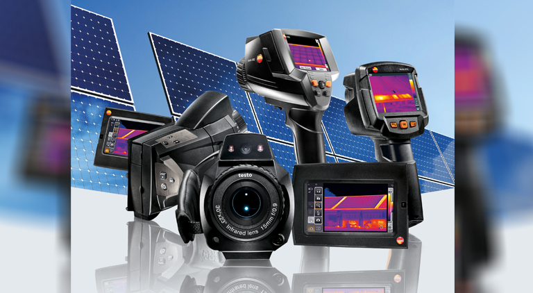
Revolutionary tool for easy assistance – Testothermal imagers
Checking photovoltaic plants using thermography places very high requirements on the use of a thermal imager. Several criteria must be taken into account when choosing a thermal imager suitable for this purpose:
Infrared resolution of the detector: An IR resolution of at least 320 X 240 pixels (76,800 measurement points) are recommended in the case of large PV systems and for measurements from a long distance.
Thermal resolution (NETD): The thermal resolution describes the capability of a thermal imager to detect temperature differences on an object surface. The lower the thermal resolution, the better the IR image generated.
Exchangeable lenses: In order to be able save time measuring large areas, e.g. from a elevated platform, imagers with exchangeable telephoto lenses should be selected that have suitable opening angles.
Camera functions: Includes various features and properties that enable the camera for easy handling and friendly usage
Software: The analysis software (e.g. testo IRSoft) enables the optimisation and analysis of the thermal images, and ensures that the findings in the images are clearly presented and documented.
Bluetooth connectivity with other devices: Interfacing of thermal imagers with temperature, humidity probes and clamp-meter for solar power analysis.
Needs and benefits of thermography
Using thermography, it is possible to check whether the quality of the module cells fulfils the requirements or not.
Incorrectly fitted or inadequately cooled electrical components that can quickly pose a fire risk can be easily traced.
Corroded or loose electrical cables indicating thermal irregularities can be easily detected and eliminated by thermography.
Solar thermography: Overview of applications and benefits
Early identification of faults, avoidance of yield loss with fast, safe inspections
Increasing operational safety, prevention of fire danger
Detecting cell rupture, corroded and loose contacts and overheated connection sockets.
Identification of hotspots, modules at open circuit, shortcircuits, delamination etc.
Creation of added value for solar engineers and plant operators.
Practical application tips
Measure in sunshine and at low outdoor temperatures
Point the thermal imager correctly, bear reflections in mind
If possible, measure on the rear
Carefully analyse the causes of temperature deviations
Selecting the right thermal imager
Observe suitable geometric and thermal resolution for the application
Imagers with exchangeable lenses and rotating display provide more flexibility
Useful functions such as solar mode and video sequence recording, as well as versatile analysis software, simplify measurement and analysis.
For more details, contact:
Email: info@testo.in
Website: www.testo.com
We use cookies to personalize your experience. By continuing to visit this website you agree to our Terms & Conditions, Privacy Policy and Cookie Policy.