A novel approach to comprehensive tests on phase-shifting transformers
By EPR Magazine Editorial May 5, 2020 2:37 pm IST
By EPR Magazine Editorial May 5, 2020 2:37 pm IST
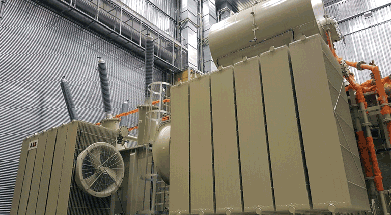
Phase-shifting transformers (PSTs) are integral to today’s power networks. We look at how symmetrical PSTs can be tested for better performance.
Today’s power systems are usually not limited to one country or region and they often comprise multiple interconnected networks from different countries. These “cross-border” connections can either enable the synchronous operation of multiple networks or establish a non-synchronous link between independently operated networks. The benefit of interconnected power systems is their mutual reserve of electric power which has become more important over the decades due to an increase in distributed energy resources (DERs).
Concurrently, there are also disadvantages such as unplanned circular flows, which can affect transmission constraints within a given area. One way to control this type of phenomena is the installation of phase-shifting transformers (PSTs), which are capable of controlling the active and/or reactive power flow in synchronous connections. This article focuses on symmetrical phase-shifting transformers by explaining their general operating principle and how they can be tested.
Operating principle for symmetrical PSTs
To regulate the active power flow across a certain line, phase-shifting transformers are used to introduce a positive or negative phase shift between the load and the source. Figure 1 illustrates this principle in the form of a vector diagram representing the source and load side voltages. The phase shift between the two is achieved by adding a so-called quadrature voltage (U) with a 90° phase shift. The magnitude of the quadrature voltage defines the phase shift between the source and load side. To achieve this, PSTs usually consist of two transformers: A series unit and an exciting unit.
The series unit (SU) is the main element of a PST, whose primary side is connected in series to the power line and consists of two symmetrical windings between the source “S” and load “L”. The secondary winding of the SU is connected in a delta, which makes it possible to introduce a voltage with a 90° shift to compare with the supply voltage. The exciting unit (EU) is connected between the two primary windings of the series unit; it transforms the primary voltage in amplitude and phase angle, so that it can be reinduced by the SUs secondary winding. The secondary winding is equipped with an on-load tap changer (OLTC) in order to regulate the magnitude of the quadrature voltage and therefore the phase angle between the source and load side of the PST.
Phase-shifting transformer tests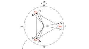
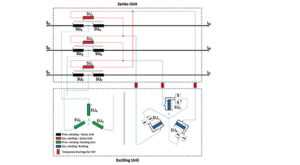
characteristic behaviour of PSTs and are usually part of any factory acceptance or on-site testing procedure. When PSTs are installed in the field, the terminals of the exciting unit are usually not accessible. Therefore, most of the time it’s only possible to conduct individual tests on the EU in the factory.
Series unit measurements
Similar to measuring the voltage ratio at different tap positions of a common network transformer, it is important to verify the specified phase-shifting range between the line terminals of the “S” and “L” sides of PST. We used our portable three-phase transformer test system, TESTRANO 600, to perform a simultaneous measurement of the phase shift, voltage turns ratio, and exciting current on all three phases. The results confirmed that the operating range was between +10° and -10° degrees with a step width of 0.87° under no-load condition.
A big challenge for testing engineers, especially during on-site commissioning testing, is determining whether the PST is operating in an advanced or retarded position. Engineers need to know if the PST is enhancing or blocking the power flow in the respective branch of the network. Making this determination is required in order to define the source and load side terminals. By using a three-phase measurement, the phase relation of the source and load side voltages and currents can conveniently be displayed in a vector diagram to determine the state of the control. An example of the results obtained at different tap positions is shown in Figure 3.
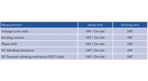
Table 1: Electrical PST tests for factory acceptance testing (FAT) and on-site testing
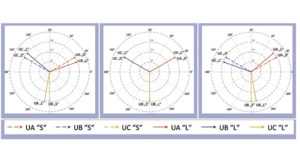
The vector interpretation of the measurement results of the phase shift control direction gives us an unambiguous indication of which of the voltage vectors on the “S” or “L” side is ahead or delayed. An additional oscilloscope recording that would require additional equipment and testing time is no longer necessary thanks to this visualisation of the measurement results.
Exciting unit measurement
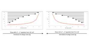
In order to illustrate the PST’s ability to regulate the magnitude of the quadrature voltage, we measured the voltage ratio of all the exciting unit’s tap positions. Figure 4 shows the ratio changing between approximately 4.5 and 54 for positions 1 through 12 and vice versa for positions 12 through 25. Positions 13A through 13B are the changeover selector’s positions for switching the regulating winding’s polarity and therefore the direction of the phase shift between the source and load side.
Conclusion
Phase-shifting transformers (PSTs) are an important part of today’s synchronous power networks. Due to the changing infrastructure of power generation, they are likely to play a key role in ensuring the reliability of power grids in the future. As PSTs are usually installed at critical nodes in the network, the time for offline maintenance should be kept as short as possible. The results have shown that using a three-phase transformer test system is a very fast and efficient way of verifying the operation parameters of a PST during commissioning and maintenance in the field.
By looking at the example of a symmetrical PST, we have shown that the described methods are suited to verify the operational principles of series and exciting units during factory acceptance testing. The same approach can also be used for an asymmetrical PST.
We use cookies to personalize your experience. By continuing to visit this website you agree to our Terms & Conditions, Privacy Policy and Cookie Policy.